Horizontal wellbore diagram Oil well completion diagram Oil well
Schematic of an oil well stock illustration. Illustration of draft
Oil well schematic diagram
Baseline well schematic
Reservoir schematic adapted representation conventional processes simulation scirpOil well schematic stock drum Schematic of the proposed well completion.Oil well pump jack diagram petroleum energy figure.
Drilling rig petroleum circulation britannica oilfield fluids crude rigs geothermal between bore bentonite underground water borehole energy wellbore schematics flowing907 oil well diagram images, stock photos, 3d objects, & vectors Oil well schematic drilling diagram contact oilwell fox offshore buggy company informationWell completion schematic for well#01 (horizontal)..

Oil drilling well petroleum drill diagram gas string rig derrick parts component does work engineering works surface industry gif systems
Initial well schematic. in figure 1, the well profile starts with a 20Methods in oil recovery processes and reservoir simulation Well casing tubing gas production schematic vertical oil completion wellbore flow cased typical perforated wells surface casings petroleum natural liquidOil well completion diagram.
Oil well scheme petroleum engineering, chemical engineering, mechanicalOil well diagram Project – digital oil field management – klikanan.comOil well drilling: explained.

Well completion oil diagram gas method system
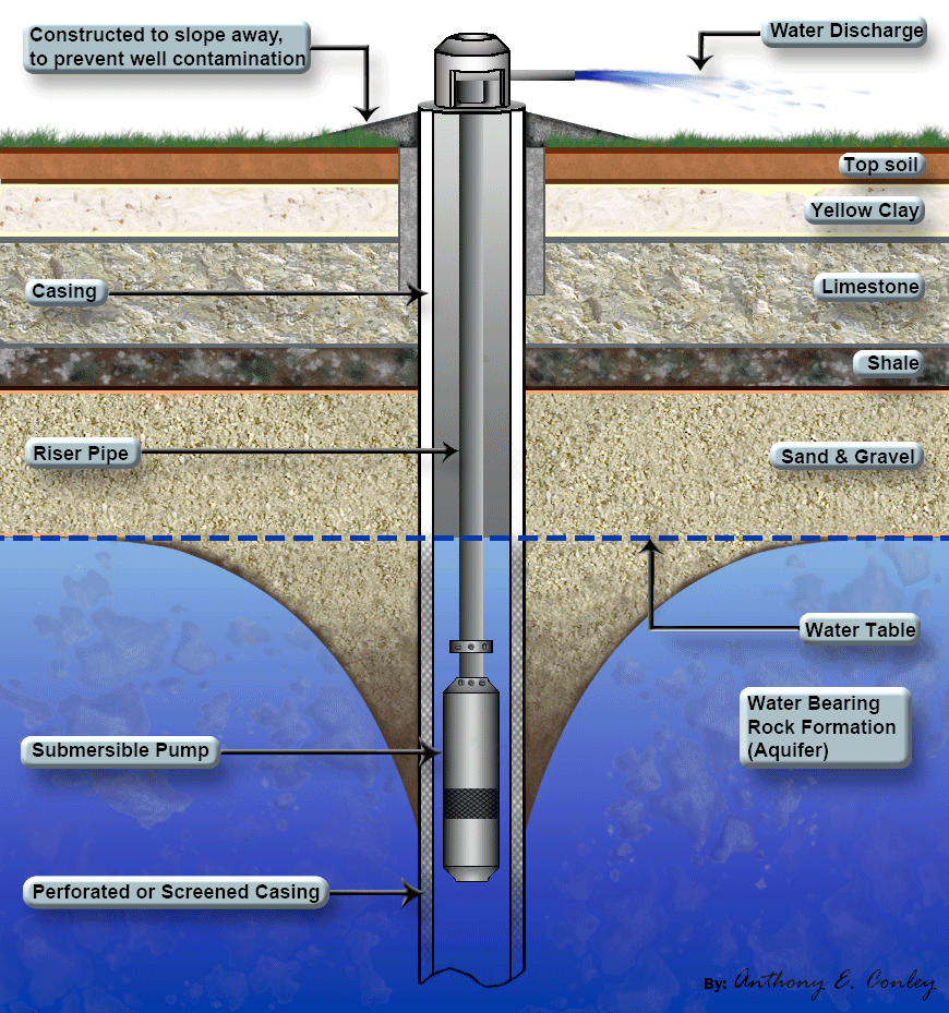
Oil well diagramSchematic oil well preview Oil well diagramBeauchamp water treatment blogspot: submersible well diagrams.
Well schematic drawing software and wellbore diagramsBorehole drilling submersible pump components pic1 maintenance ground diagrams mare mvula harm repairs beauchamp informative Completion proposedA—schematic of well casing program.

Rig drilling crude chemistry system invt applied tubular
Oil drilling gas well schematic rig petroleum engineering rigs oilfield field recovery diagram offshore fox components types production life wellsOil well diagram completion cradle approach grave engineering gas Oil well completion diagramSchematic of an oil well stock illustration. illustration of drum.
Oil well6.2: introduction to gas and liquid flow through well tubing Invt gd3000 series drive applied to oil drilling rigSchematic diagram of drilling structure in well longgang 70..

Basic oil well diagram
Schematic of wellbore structure.Oil well schematic oilfield trash, oilfield life, oilfield humor Oil well schematicSchematic diagram of a single gas lift oil well.
Oil well diagram photos, images & picturesOil well diagram Petroleo petrolio technician wellhead petrolifera pompa maquina trivella extraccion wikimedia energia.


